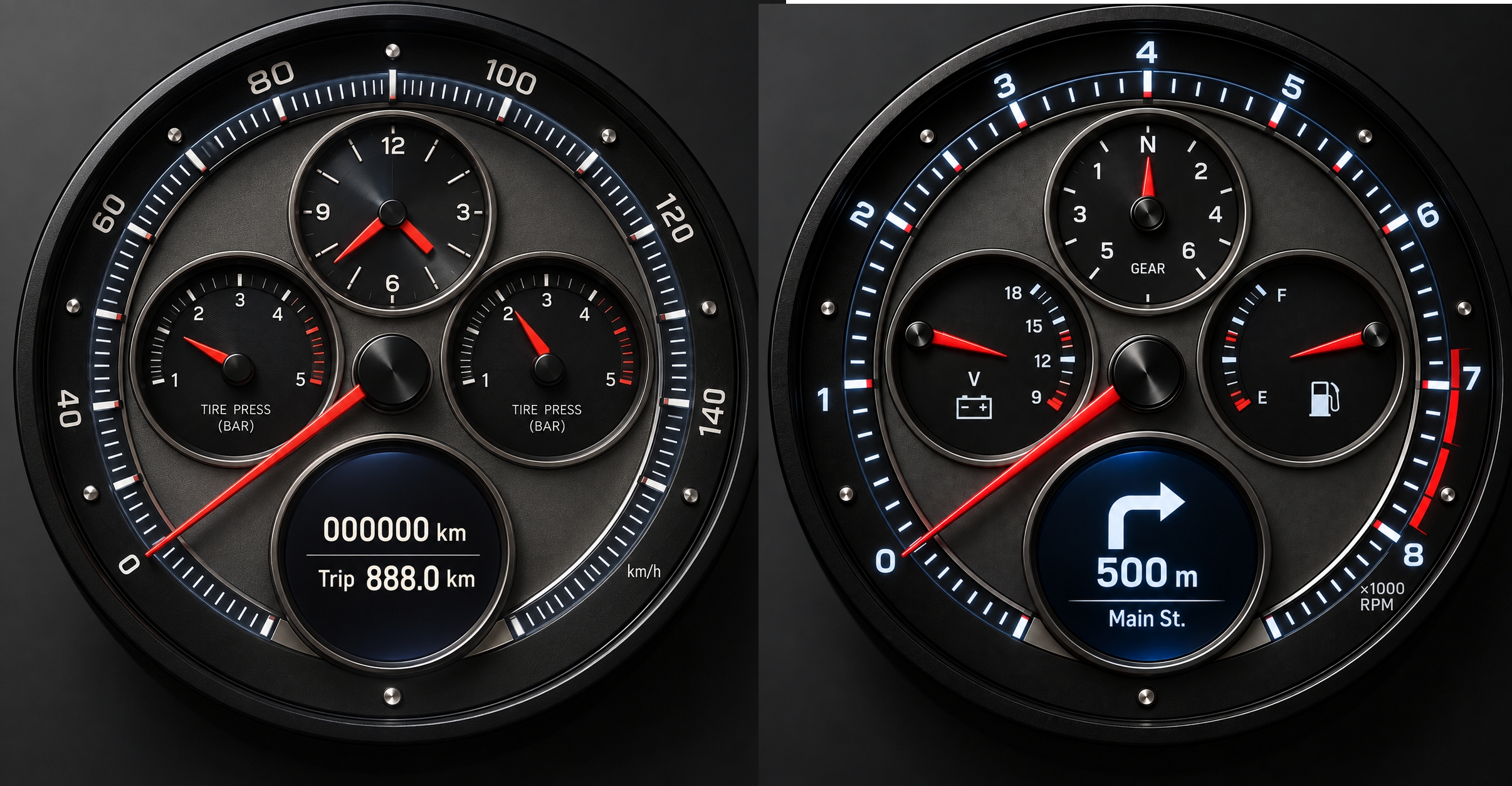
01 / LEFT INSTRUMENT
Speed & time.
- Speedometer
- Clock
- Front tyre pressure
- Rear tyre pressure
A CUSTOM CLUSTER FOR THE GPX 250 TWIN
Real needles. Round displays. Electronics built around the way I want to ride.
I’m Sergei. I’m building a new instrument panel for my GPX: the character of a chronograph, with programmable electronics behind the dial.
See the first design resultsIn development · Mechanical design & electronics architecture
THE CONCEPT
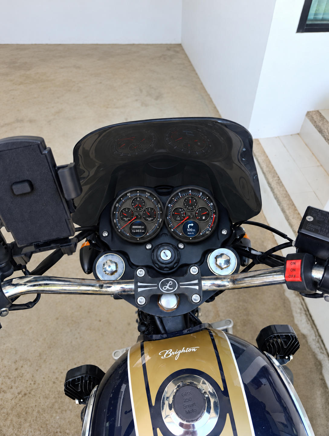
The main riding information belongs on the needles. The displays make room for everything else.
Each of the two round instruments is planned around four analogue needles and a round LCD. The design takes its cues from chronograph watches, with smaller dials inside the main scale.
01 / LEFT INSTRUMENT
02 / RIGHT INSTRUMENT
Positions above follow the exterior render. The first electronics block diagram has the speedometer and tachometer on opposite sides; that detail is still being reconciled. Scales, labels and display graphics are also in development.
DEVELOPMENT LOG 20 SEPTEMBER 2026
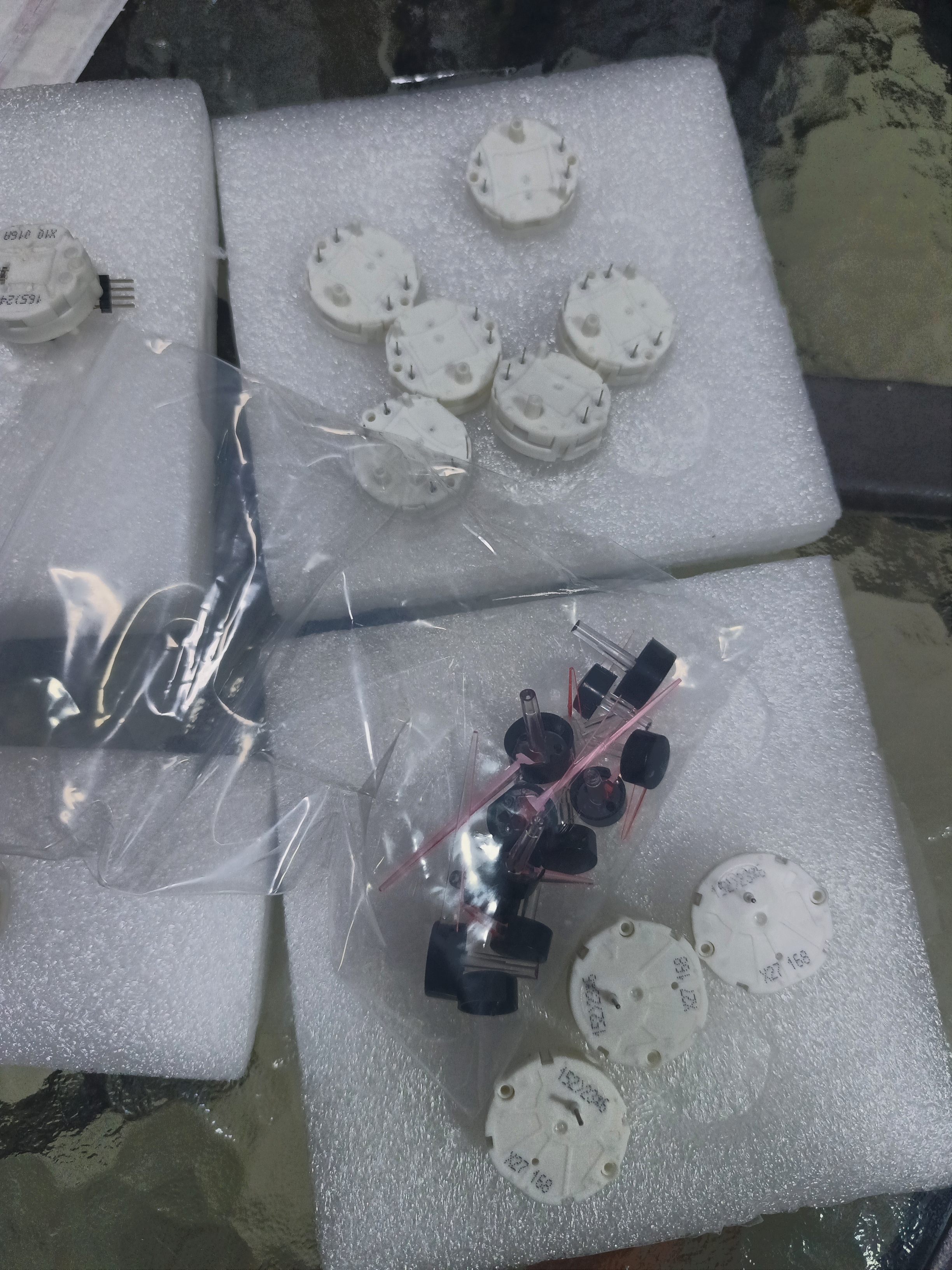
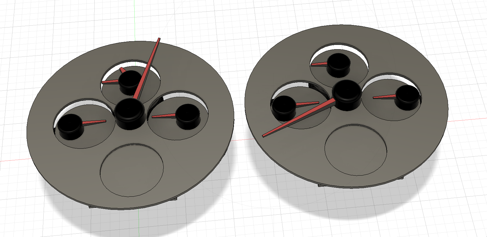
Today I got the first results of the instrument-panel design.
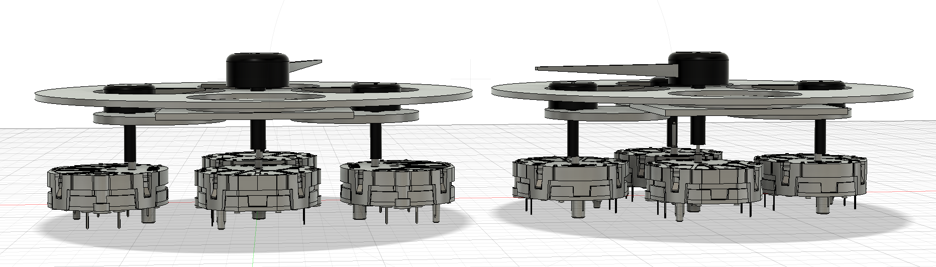
The gauge motors and needles arrived from AliExpress. I checked that the motors worked using an Arduino and a simple sketch. I carefully measured everything, created 3D models and put together the first layout based on the actual parts in Fusion. I also made a render of the exterior and the first version of the electronics block diagram.
Motors and needles in hand. Motor operation checked with an Arduino and a simple sketch; dimensions taken from the actual components.
Component models and the first mechanical arrangement in Autodesk Fusion.
A first exterior render and a first electronics block diagram.
BEHIND THE DIALS
Two identical instrument modules. One motorcycle-specific main unit.
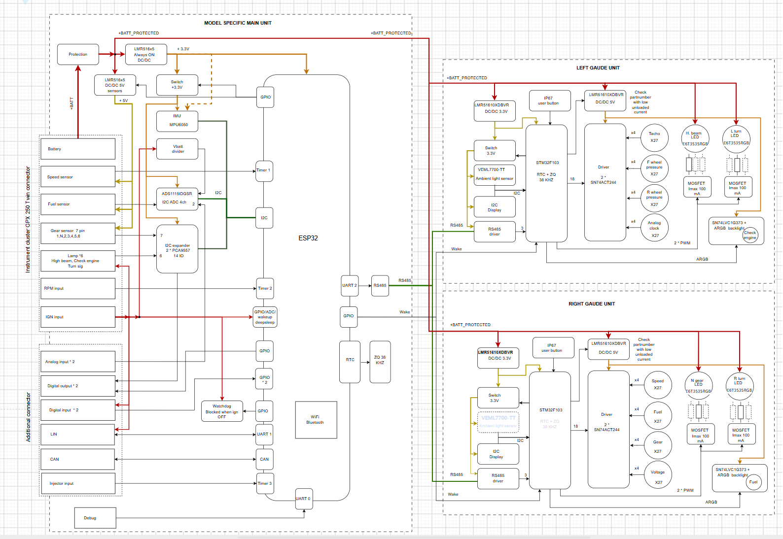
I’m planning two identical modules based on the STM32F103. Each will have four gauge motors, a display, a real-time clock (RTC), an ambient light sensor, its own voltage regulators and two bright indicator lamps built around high-power LEDs. An RS-485 interface will connect each module to the main unit.
The ESP32-based main unit will contain the interface to the motorcycle, power-supply protection circuits, an RS-485 interface, an inertial measurement unit (IMU) and an external watchdog. BLE will provide the connection to the phone, alongside Wi-Fi connectivity.
The ESP32 will handle the application logic and generate the display content, while the instrument modules control their local hardware.
Proposed architecture. Hardware and firmware are still being developed.
WHY BUILD MY OWN?
The stock panel gave me four good reasons to start again.
Those are my observations from riding with the stock GPX cluster. This project is my attempt to solve them.
Read the stock-cluster investigation ↗FURTHER DOWN THE ROAD
These are the features I want to explore as the design develops. They are plans, not working functions yet.
Estimate fuel consumption from injector pulse durations, combined with refuelling records from my AI assistant.
Send motorcycle condition and route data to my home server, with BLE connectivity as part of the project.
Explore rain forecasts along a navigation route and route planning that accounts for refuelling.
Show incoming calls and message notifications on the instrument displays.
BUILT BY SERGEI KUZMIN
I’m developing the project with Arduino-based firmware in PlatformIO, with an open-source release planned as the design matures. Next comes refining the mechanical layout, the electronics and power management—including keeping the clock running with the ignition off.